401 Authorization Required

This server could not verify that you are authorized to access the document requested. Either you supplied the wrong credentials (e.g., bad password), or your browser doesn't understand how to supply the credentials required.

Additionally, a 401 Authorization Required error was encountered while trying to use an ErrorDocument to handle the request.
Graynomad:
I get the same. It's either a bad link or not open to the public (can't imagine why and if so the link shouldn't be there in the first place).
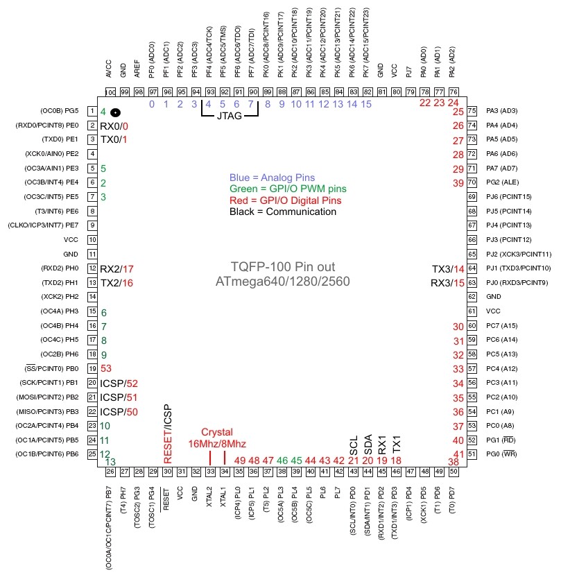
Thanks for confirming - hopefully, someone can either open up this link or remove it; otherwise I hope someone will be able to post something "third party" like the ATmega328 image in Arduino Forum - Arduino Mega2560 Pin Names...
Is there a discrepancy between your pin mapping picture and the arduino reference on user interrupt numbers Vs pin numbers? It's probably based on the fact that the arduino external interrupt numbers (0-5) have no direct association with the AVR external interrupt names. This is sure to confuse sometimes what mega pins numbers to wire to utilize a given arduino attachinterrupt function. See the below Arduino reference extract for the arduino's assignment of interrupt names (0-5) to mega pin numbers, and see the possiblity of confusion.
attachInterrupt(interrupt, function, mode)
Description
Specifies a function to call when an external interrupt occurs. Replaces any previous function that was attached to the interrupt. Most Arduino boards have two external interrupts: numbers 0 (on digital pin 2) and 1 (on digital pin 3). The Arduino Mega has an additional four: numbers 2 (pin 21), 3 (pin 20), 4 (pin 19), and 5 (pin 18).
retrolefty:
Is there a discrepancy between your pin mapping picture and the arduino reference on user interrupt numbers Vs pin numbers?
Could well be - as I noted, I didn't really go through the ATMega datasheets myself, instead I just copied the data from this Arduino Pins spreadsheet, the link for which I found elsewhere on the web...
retrolefty:
It's probably based on the fact that the arduino external interrupt numbers (0-5) have no direct association with the AVR external interrupt names. This is sure to confuse sometimes what mega pins numbers to wire to utilize a given arduino attachinterrupt function. See the below Arduino reference extract for the arduino's assignment of interrupt names (0-5) to mega pin numbers, and see the possiblity of confusion.
attachInterrupt(interrupt, function, mode)
Description
Specifies a function to call when an external interrupt occurs. Replaces any previous function that was attached to the interrupt. Most Arduino boards have two external interrupts: numbers 0 (on digital pin 2) and 1 (on digital pin 3). The Arduino Mega has an additional four: numbers 2 (pin 21), 3 (pin 20), 4 (pin 19), and 5 (pin 18).
Ok, I see what you mean - I guess that is from Arduino - AttachInterrupt; could be that was written for the ATmega1280, and I copied data for the ATmega2560? Unfortunately, the spreadsheet doesn't say... At least, on the pin map image, digital pins D3, D2, D18, D19, D20, D21 all have "INT" or "ext int" numbers, so at least that is right - but I can see what you mean by the interrupt number confusion..
In any case, if anyone has a suggestion which particular text in the map image I should change, I will eventually do so (I currently do not work with external interrupts, so it may be a while until I figure out possible errors myself)..
Ok, I see what you mean - I guess that is from Arduino - AttachInterrupt; could be that was written for the ATmega1280, and I copied data for the ATmega2560?
The only differences from the AVR mega1280 and mega2560 is the increase in the various memory sizes (flash,sram,eeprom) for the 2560, all internal hardware peripherals and pin assignments are the same.
Thanks for putting up the PinMapping. I too was frustrated looking for a pin mapping for any of the Arduino Mega boards. Why they hid the essential design information needed to use the board is a complete mystery to me.