::Delta Movement Robot::
Concept
This robot is an exploration of a delta movement being used to make a mobile robot. Some examples of delta robots are a high speed version on youtube and a project polybot on thingiverse. Both of which inspired this design. During final assembly the mount the servos on the table and it turned out much easier mount as the base. This changed the robot so that it lifts up its polyhedron frame and places it to its side then lifts its own servos and power source over to the new location.
The primary advantage with this design is the robot can head whatever direction it deems best without having to turn in the sand. Basically the movement allows for the movement in arbitrary directions without energy turning on the sound.
Figure 1 shows a picture of the delta robot. Figure 2 and 3 show close ups of the linkage between the servos and the linkage pieces.
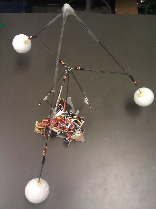
Figure 1 A picture of the entire robot
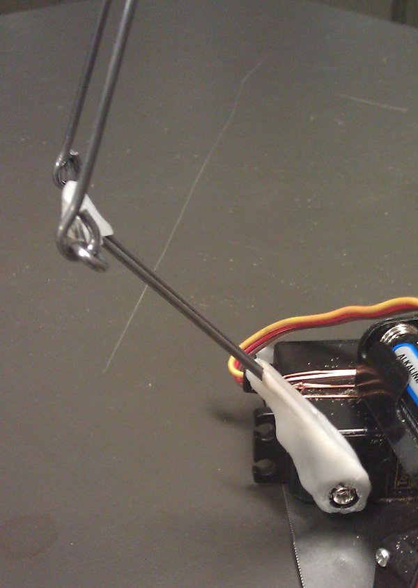
Figure 2 A close up of the linkage between the servo and the t-bar that is the first piece of the linkage.

Figure 3 A close up of the linkages all joined together in another equilateral triangle. The linkage pieces were steel wire bent into loops.
Hardware Layout
The hardware layout is pretty simple. The three servos are arranged at the edge of a equilateral triangle. The servos are then mounted to this equilateral triangle. In this prototype the servos are wired to the bottom plate which is the equilateral triangle.
Attached to each servo is a T bar. It was made by bending a single piece of steel wire into a T shape then bending to small hoops on the end. These hoops were made using a pair of pliers that are used for making jewelry. The T bar is then mounted to the horn of the servo using ShapeLock. See Figure 2 for some detail on this piece.
The ends of T bar is connected to a much small equilateral triangle on the frame. See Figure 3 for details of the linkage piece.
The length of the T bar and the linkage piece can be made in many different sizes.
Software
- #include <Servo.h>
- Servo A,B,C;
- #define AMax 180
- #define AMin 80
- #define BMax 180
- #define BMin 80
- #define CMax 180
- #define CMin 80
- #define time 300
- int APos,BPos,CPos;
- long start;
- void setup()
- {
- Serial.begin(9600); // start serial for output
- APos=(AMax+AMin)/2;
- BPos=(BMax+BMin)/2;
- CPos=(CMax+CMin)/2;
- A.write(APos);
- B.write(BPos);
- C.write(CPos);
- A.attach(10);
- B.attach(11);
- C.attach(12);
- delay(15);
- start=millis();
- }
- void update()
- {
- A.write(APos);
- delay(25);
- B.write(BPos);
- delay(25);
- C.write(CPos);
- delay(25);
- }
- void up() {
- APos=AMax;
- BPos=BMax;
- CPos=CMax;
- update();
- delay(time);
- }
- void down() {
- APos=AMin;
- BPos=BMin;
- CPos=CMin;
- update();
- delay(time);
- }
- void moveA() {
- APos=(AMax+AMin)/2;
- BPos=BMin;
- CPos=CMin;
- update();
- delay(time);
- up();
- }
- void moveB() {
- APos=AMin;
- BPos=(BMax+BMin)/2;
- CPos=CMin;
- update();
- delay(time);
- up();
- }
- void moveC() {
- APos=AMin;
- BPos=BMin;
- CPos=(CMax+CMin)/2;
- update();
- delay(time);
- up();
- }
- void exercise() {
- down();
- up();
- }
- void loop() {
- long dt=millis()-start;
- Serial.print("dt=");
- Serial.println(dt);
- if (dt<10000) {
- exercise();
- }
- else if (dt<20000) {
- moveA();
- }
- else if (dt<30000) {
- moveB();
- }
- else if (dt<40000) {
- moveC();
- } else {
- up();
- }
- }
What is next
We have a plan add sensors in the three primary directions, and possibly in three intermediate directions. Then modify the software so the robot can move around obstacles.