IEE Flip 03700-06-020/S
The IEE Flip 03700-06-020/S VFD (vacuum fluorescent display) module is a large, bright, retro display capable of displaying 1 row of 20 character wide text. The display pictured below was manufactured in 1994 and was purchased as pristine, factory fresh, new old stock. The design and components were already dated by 1994 - the microcontroller has a copyright date of 1977. The display can be used with Arduino via the IeeFlip library.
The details on this page were arrived at by piecing together information from the datasheets linked to at the bottom of this page, the label on the back of the display and experimentation.
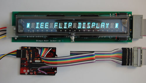
VFD module being driven by the IeeFlip library. The Arduino compatible board shown is a Diavolino from Evil Mad Science.
Wiring

Bottom of the display board.

Top of the board with the tube removed. Removal of the tube is not recommended as it may be damaged in the process. It was carefully removed in this case for photographic and examination purposes.
Power
According to the label on the back of the display, power is 5v @ 600ma. The power connector is the white two-pin connector labelled P1 and is located on the top side of the board. The connector can be seen to the left in the above board image: +5v is the top pin and ground is the bottom pin.
Note that the image at the top of the page shows power connected via a computer molex power connector. This was done just for testing, it is not secure enough for normal use.
Caution: While the display operates on 5V, higher voltages are generated on board. As with all VFDs, the display board should not be operated outside of an appropriate enclosure.
Control/Data Connector
This display's control/data connection is via a 26 pin edge connector. Half of the pins are connected to ground. If an edge connector socket is not available, a standard double row pin header can be soldered to the display connector. The pinout is as follows:
| Pin # | Name |
|---|---|
| 1 | /TEST* |
| 2 | GND |
| 3 | /CS |
| 4 | GND** |
| 5 | /RD |
| 6 | GND |
| 7 | A0 |
| 8 | GND |
| 9 | /WR |
| 10 | GND |
| 11 | D0 |
| 12 | GND |
| 13 | D1 |
| 14 | GND |
| 15 | D2 |
| 16 | GND |
| 17 | D3 |
| 18 | GND |
| 19 | D4 |
| 20 | GND |
| 21 | D5 |
| 22 | GND |
| 23 | D6 |
| 24 | GND |
| 25 | D7 |
| 26 | GND |
 * On some other IEE Flip models, pin 1 is also SERIAL IN
 ** On some other IEE Flip models, pin 4 is /INT rather than ground
The display board has 10k pull-up resistors on /TEST, /CS, /RD, A0, /RD.
Testing
Before fully wiring up the display it can be tested by connecting the /TEST pin to ground and applying power to the power connector. The display should power up and output the character set at approximately 1 character per second. In normal usage, /TEST can be left unconnected.
Driving from Software
Overview
The display features an 8 bit parallel interface. Data sent to the display at address 0 (A0 low) is interpreted as character data and displayed at the current cursor position.
Control Characters
Characters in the hexadecimal range 08h to 1Fh are special control characters.
- 08h - Backspace. Moves cursor location back (leftward) one position
- 09h - Tab. Moves cursor location forward (rightward) one position
- 0Ah - Line feed. In effect, clears the display without changing cursor location
- 0Bh - Begin blinking characters. Following characters will blink on and off
- 0Ch - End blinking characters. Following characters will not blink (display constantly). This is the power on default
- 0Dh - Carriage return. Moves the cursor to the leftmost location
- 0Eh - Blinking cursor off. This is the power on default
- 0Fh - Blinking cursor on. A filled rectangle will blink on and off at the current cursor location.
- 11h - End of line mode = wrap. When the cursor advances past the end of the line, it will move to the start of the line. This is the power on default
- 12h - End of line mode = stop. When the cursor reaches the end of the line, it will advance no further
- 13h - End of line mode = scroll. When the cursor advances past the end of the line the display text will scroll horizontally
- 1Bh - Set cursor location. The cursor will be set to the location specified by the next value sent to the display
Timing of Read and Write Operations
Read and write cycle timing is defined in the datasheet for the Intel P8042AH (see link below). In addition the display requires delays between operations, the amount of time being dependent on the operation. The requirements for this display is not known, the IeeFlip library uses the worst-case timings from the newer IEE datasheet linked to below.
Addressing
It is not known whether writing to address 1 (A0 high) has any effect on the display. Experimentation did not result in any apparent change to the display. A0 may be tied directly to ground.
Reading
It is not known whether the display returns any useful data. In experimentation reading from the display always returned zero. /RD may be left unconnected.
Character Set
- 20h to 7Eh - Approximation of standard ASCII characters.
- 7Fh - Filled rectangle
- 80h to 9Fh - Identical to 20h to 3Fh but with comma set
- A0h to DFh - Identical to 20h to 5Fh but with decimal point set
- E0h to FFh - Identical to 40h to 5Fh but with comma set
More Information
- Datasheet for 03601-02-040 display which is of similar vintage and operation
- Search for Intel P8042AH datasheet, the slave microcontroller used by this display
- Datasheet for newer dot matrix based IEE Flip displays. Little information applies directly however the document provides some insight
- IeeFlip library
- BG Micro where this display was acquired